| OVERVIEW
This is a simple design tool for calculating bias resistor values,
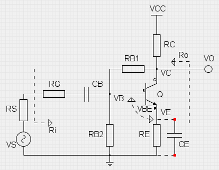
small-signal gain and input/output resistances of a common-emitter BJT amplifier
with collector-to-base (+ emitter) feedback.
Just fill the input fields below in given order from top to bottom.
The ordering of the fields
serves as a step-by-step guide for the design process.
The base bias resistor values are calculated automatically (using 5% tolerance resistances),
but custom values can be given and those will not be overwritten.
The 'Calculate values' button in the bias resistor field always rounds up
to the nearest 5% tolerance, even user defined values.
The small-signal values are evaluated in the mid-band, CB short-circuited.
CE can be included using the selection box.
The small-signal gain is evaluated as VO/VS, and the input/output
resistances are evaluated as shown. |
 |
| Select the operating voltage VCC. Typically 9 volts is the way to go. |
VCC : |
volts |
RESULTS
DC Bias voltages:
VC : volts
VE : volts
VB : volts
AC Voltage Gain factor:
Av : const
dB
AC Input resistance:
Ri : ohms
AC Output resistance:
Ro : ohms
|
| Select the BJT you want to use, from its datasheet
lookup the current gain factor and place it here as a parameter. |
hFE : |
const |
| For convenience, you can change the base-emitter voltage,
which is set to 0.65 V by default.
Typical VBE is 0.55 - 0.75 V. |
VBE : |
volts |
| Choose the collector bias voltage to aim for.
Typically the collector bias voltage is half of the operating voltage VCC. |
VC : |
volts |
| The collector resistor RC should be chosen to limit collector current to the suitable level.
RC affects base bias and the output impedance. |
RC : |
ohms |
| Next select a value of the emitter resistor.
RE reduces gain, but it helps to stabilize the DC bias voltages and
it also slightly increases the input and output impedances. |
RE : |
ohms |
| A multiplier for base resistor values, which are obtained in the next step.
Too much resistance at the base affects the stability of biasing.
Use values between 2 - 60. |
Bx : |
const |
The biasing is finalized by setting a voltage divider on the base.
By pressing the button below, the bias resistor values are calculated automatically.
Values have to be cleared before recalculation.
|
RB1 :
RB2 :
|
ohms
ohms |
| Next determine AC gain by choosing a value for RG.
Just like the op-amp gain, here RG interacts with the feedback resistor RB1.
The gain of this configuration is approximately RB1/(RG+RS),
but the added emitter resistor decreases the gain from this value. |
RG : |
ohms |
| Also, the internal resistance of the signal source should be given.
For ideal source this value is small,
but for guitar output this is a few kilohms. |
RS : |
ohms |
Use CE for RE bypass |