| OVERVIEW
This is a simple design tool for calculating bias resistor values,
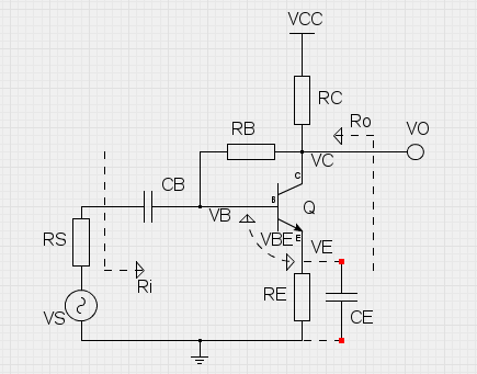
small-signal gain and input/output resistances of a common-emitter BJT amplifier
with collector-to-base (+emitter) feedback.
Just fill the input fields below in given order from top to bottom.
The ordering of the fields
serves as a step-by-step guide for the design process.
The base bias resistor values are calculated automatically (using 5% tolerance resistances),
but custom values can be given and those will not be overwritten.
The 'Calculate values' button in the bias resistor field always rounds up
to the nearest 5% tolerance, even user defined values.
The small-signal values are evaluated in the mid-band, CB short-circuited.
CE can be included using the selection box.
The small-signal gain is evaluated as VO/VS, and the input/output
resistances are evaluated as shown.
|
 |
| Select the operating voltage VCC. Typically 9 volts is the way to go. |
VCC : |
volts |
RESULTS
DC Bias voltages:
VC : volts
VE : volts
VB : volts
AC Voltage Gain factor:
Av : const
dB
AC Input resistance:
Ri : ohms
AC Output resistance:
Ro : ohms
|
| Select the BJT you want to use.
From the datasheet of the chosen transistor,
lookup for the typical current gain factor and place it here as a parameter. |
hFE : |
const |
| For convenience, you can change the base-emitter voltage,
which currently is set to 0.65 V by default.
Typically VBE is around 0.55 - 0.75 V. |
VBE : |
volts |
| Choose the collector bias voltage to aim with the biasing design.
In a normal design the collector bias voltage is half of the operating voltage VCC. |
VC : |
volts |
| Next select a value of the collector resistor.
RC should be mainly chosen to limit collector current to the suitable level.
The value of RC affects the base bias resistor values and output impedance. |
RC : |
ohms |
| Next select a value of the emitter resistor.
RE decreases gain, but increases the bias stability and input impedance. |
RE : |
ohms |
The biasing is finalized by setting a feedback resistor between collector and base.
By pressing the button below, the bias resistor value is calculated automatically.
|
RB : |
ohms |
| Also, the internal resistance of the signal source should be given.
For ideal source this value is small,
but for guitar output this is a few kilohms. |
RS : |
ohms |
Use CE for RE bypass |